3.0 - Blink
Building on our Blink skillz, lets build a LED circuit and control it with UNO!
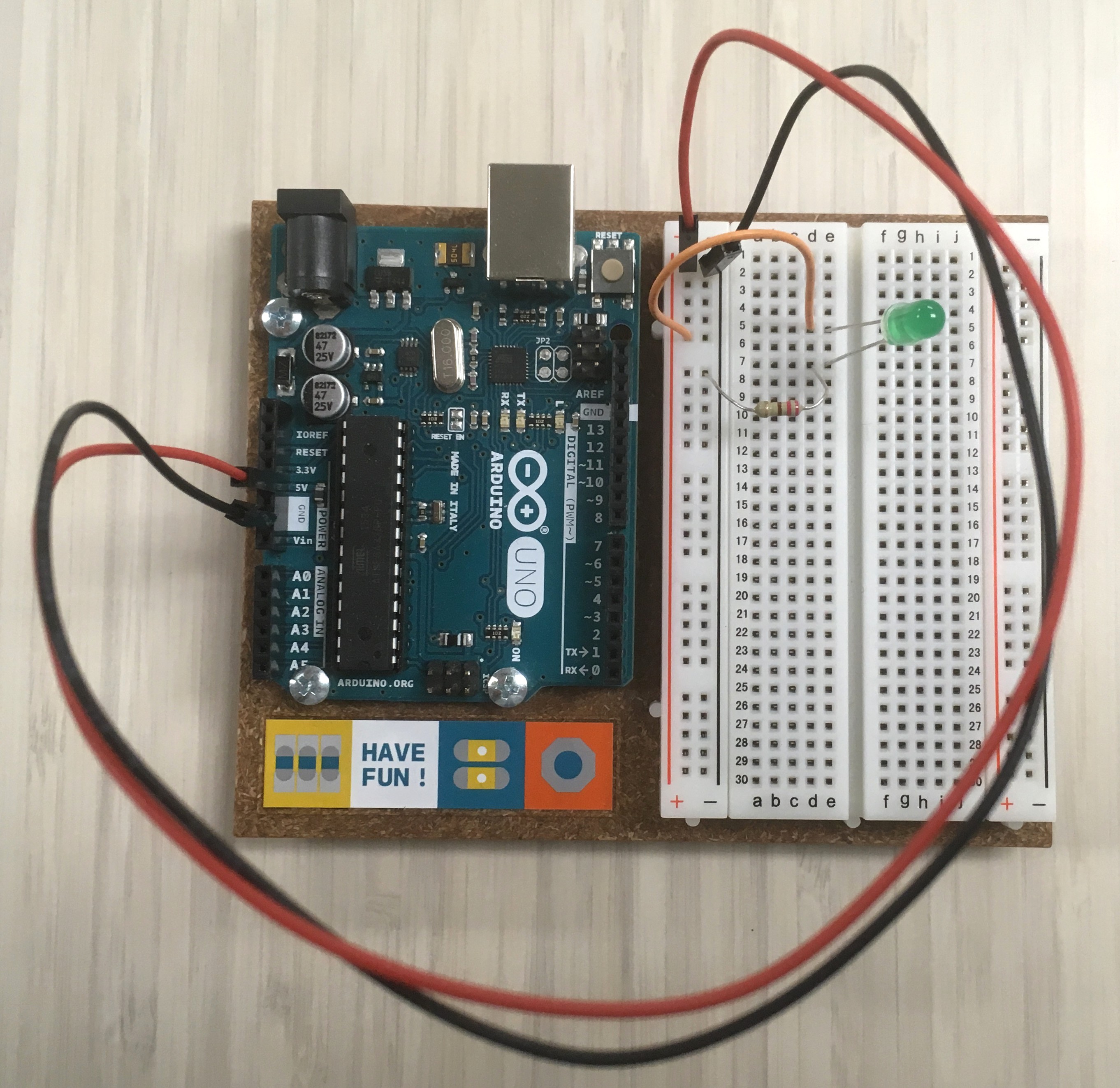
For this project you will need a breadboard, some jumper wires, a 220 or 330 ohm resistor, and an LED.
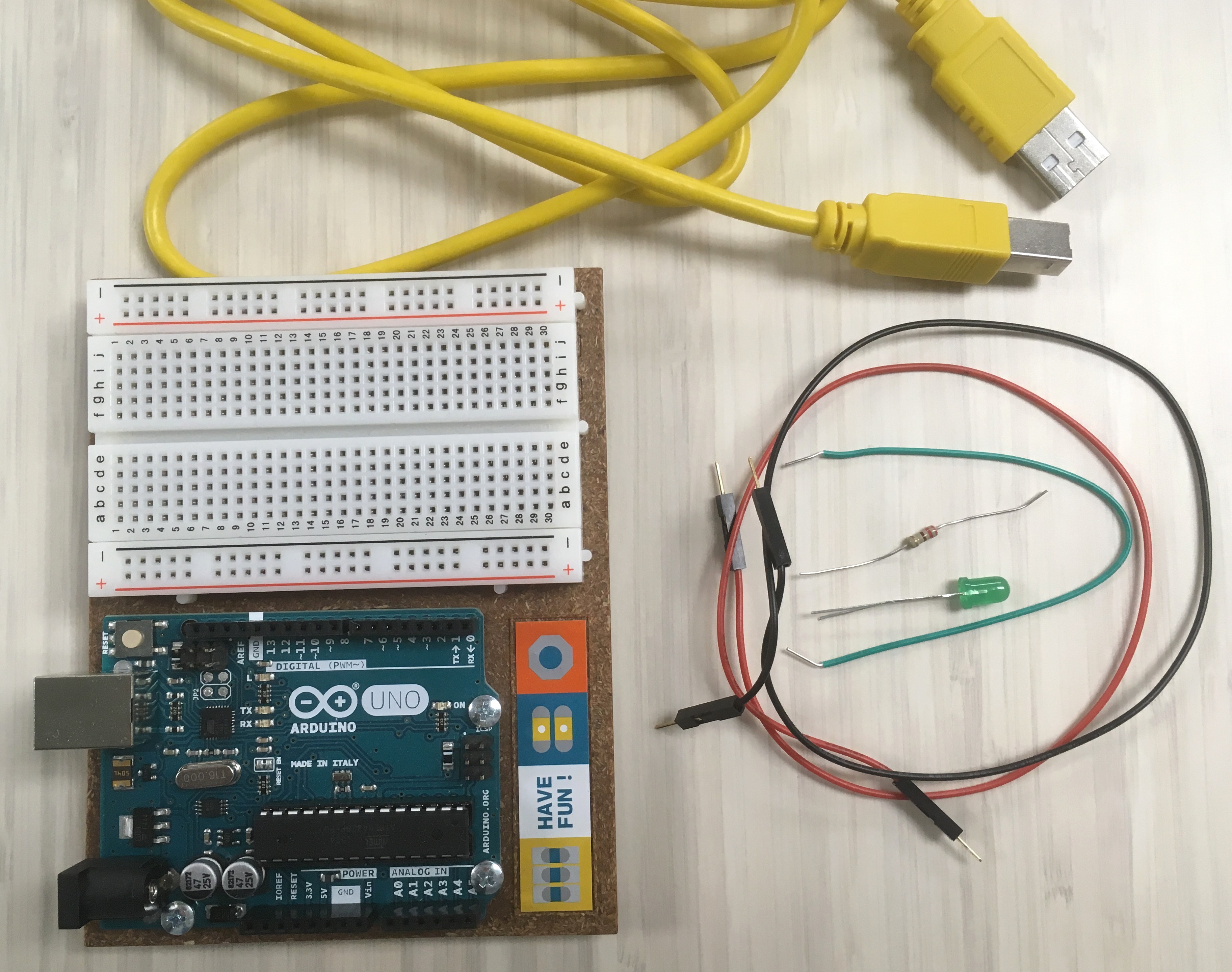
Know your LED: the longer leg is the
anodeand connects to positive voltage, i.e.+or5V; the short leg is thecathodeand connects to ground, i.e.-orGND.
Know your resistor: resistors are marked by color bands, but they are often hard to read - check them with a multimeter.
3.1 - First circuit
-
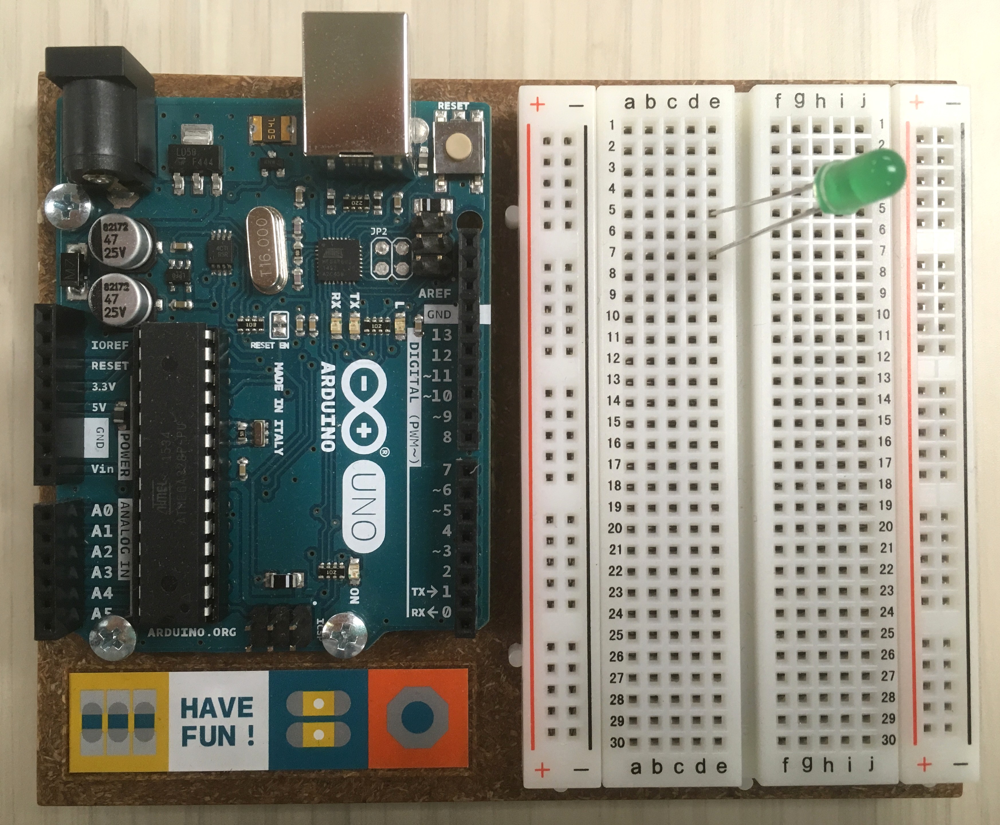
Gently push the legs of your LED into two different rows on the breadboard. Remember which one is the long leg!
-
Connect the LED
cathode(short leg) toGNDby inserting the legs of a 220 ohm resistor into the row and the-Rail.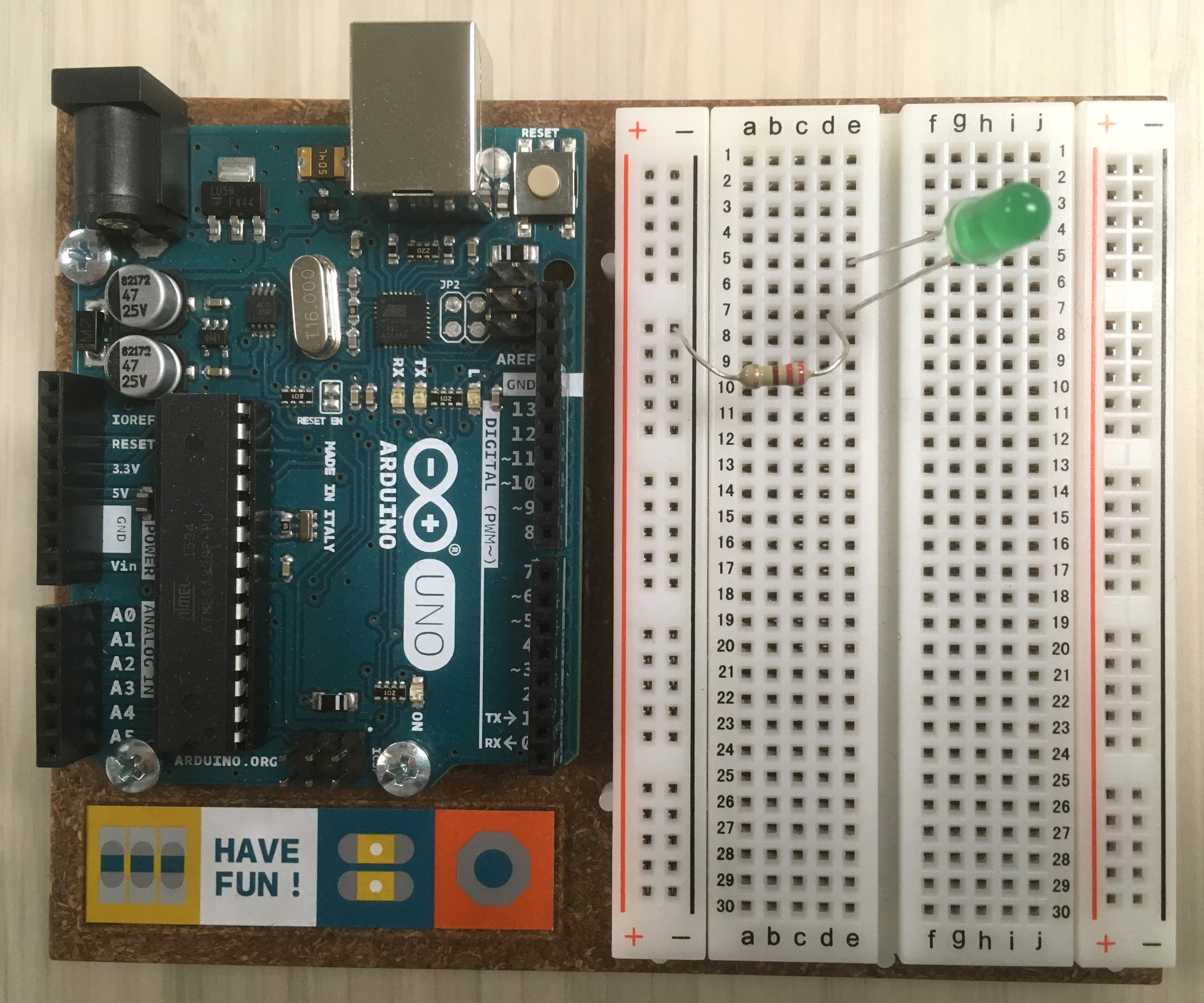
-
Connect the LED
anode(long leg) to5Vby inserting a jumper wire into the row and the+Rail.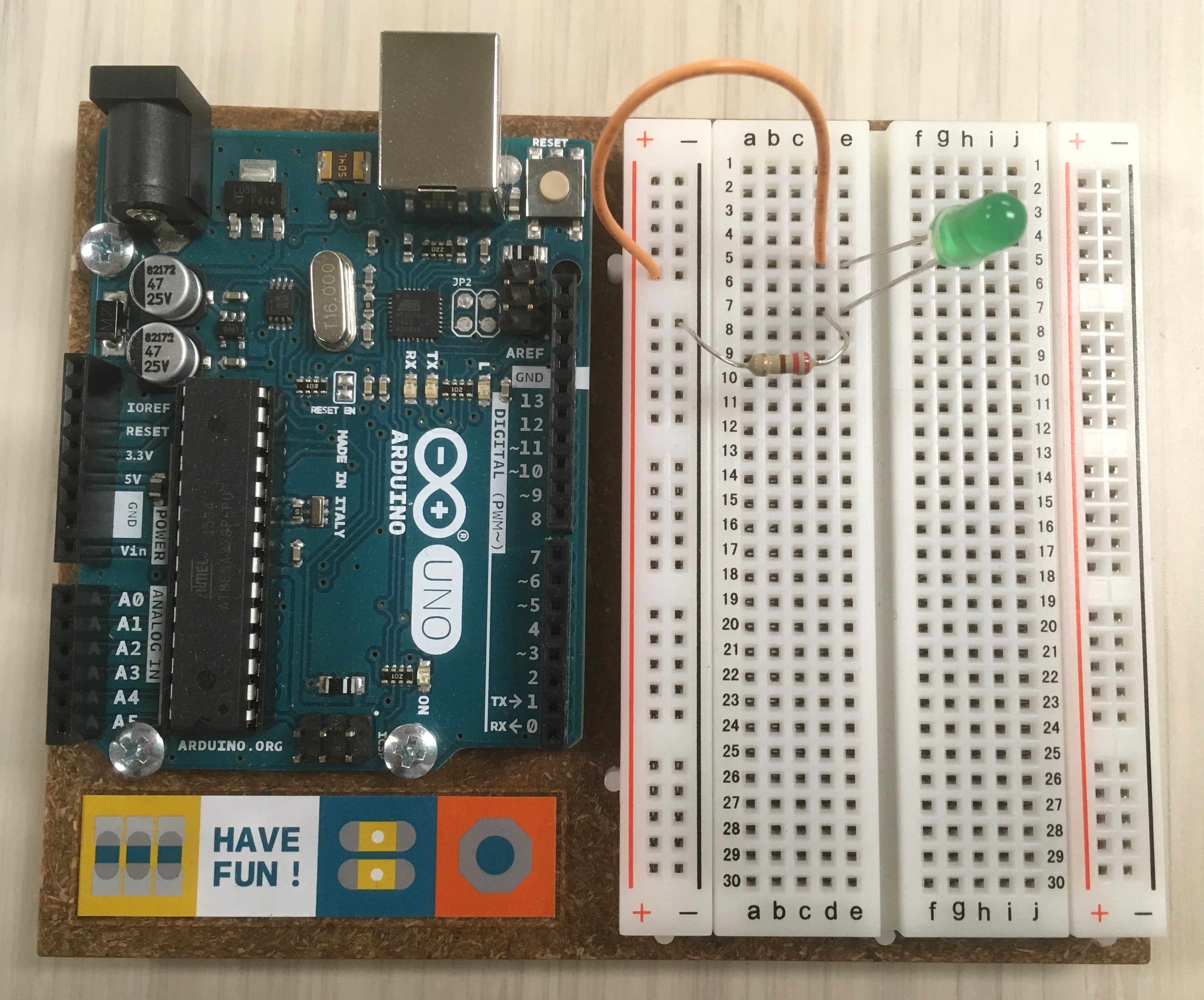
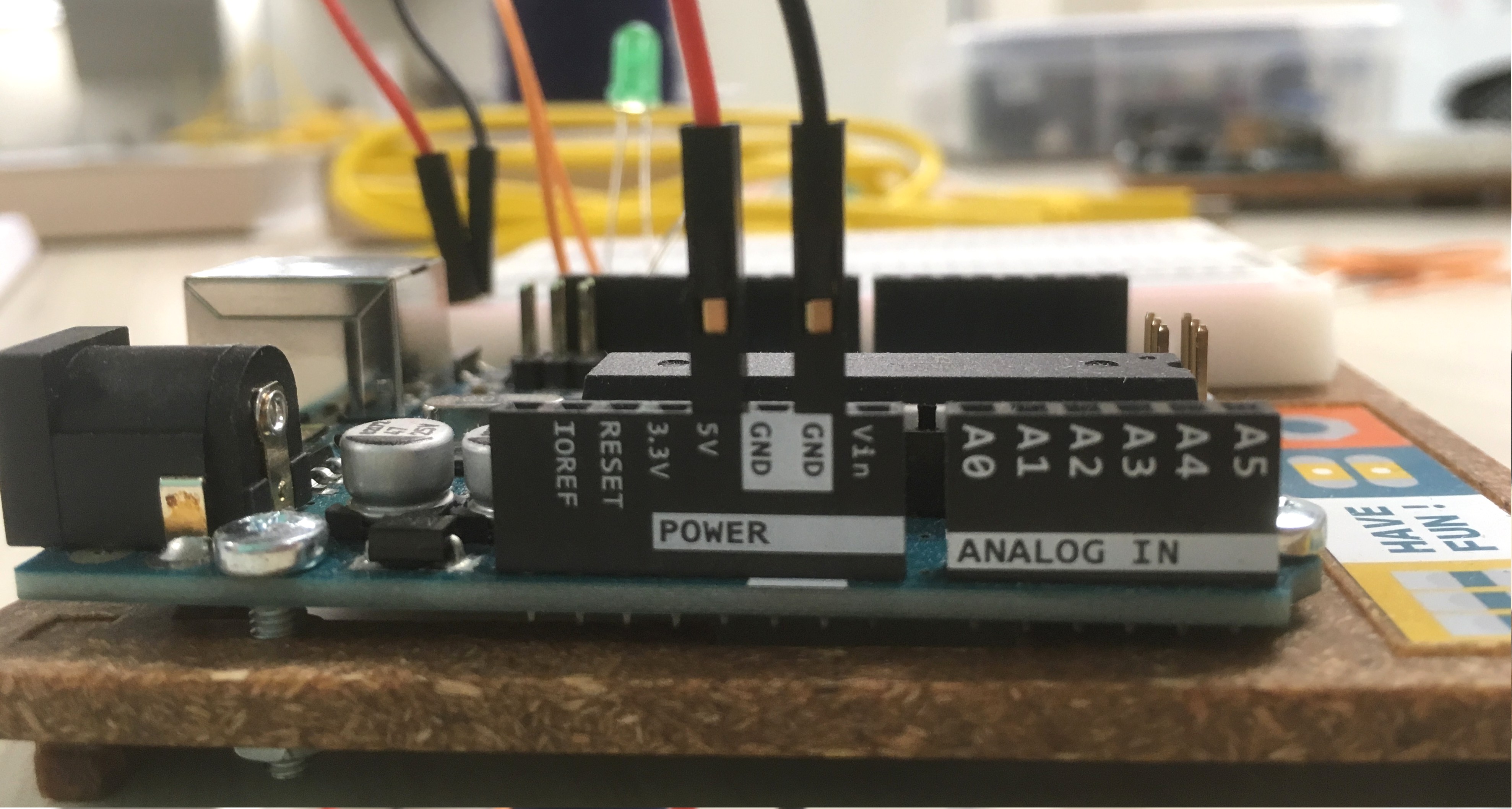
- Connect the breadboard to the UNO’s power supply:
- use a red jumper wire to connect the
+rail to the pin labeled5Von the UNO. - use a black jumper wire to connect the
-rail to any pin labeledGNDon the UNO (you have 3 choices).
- use a red jumper wire to connect the
- Plug your UNO into your usb cable.
You should now have a beautiful glowing LED!
3.2 - Blink it!
This circuit is drawing power from UNO, but it is not controlled by it. We need to connect the LED to a pin so we can start blinking!
-
Unplug the wire connecting the
anodefrom the+rail. -
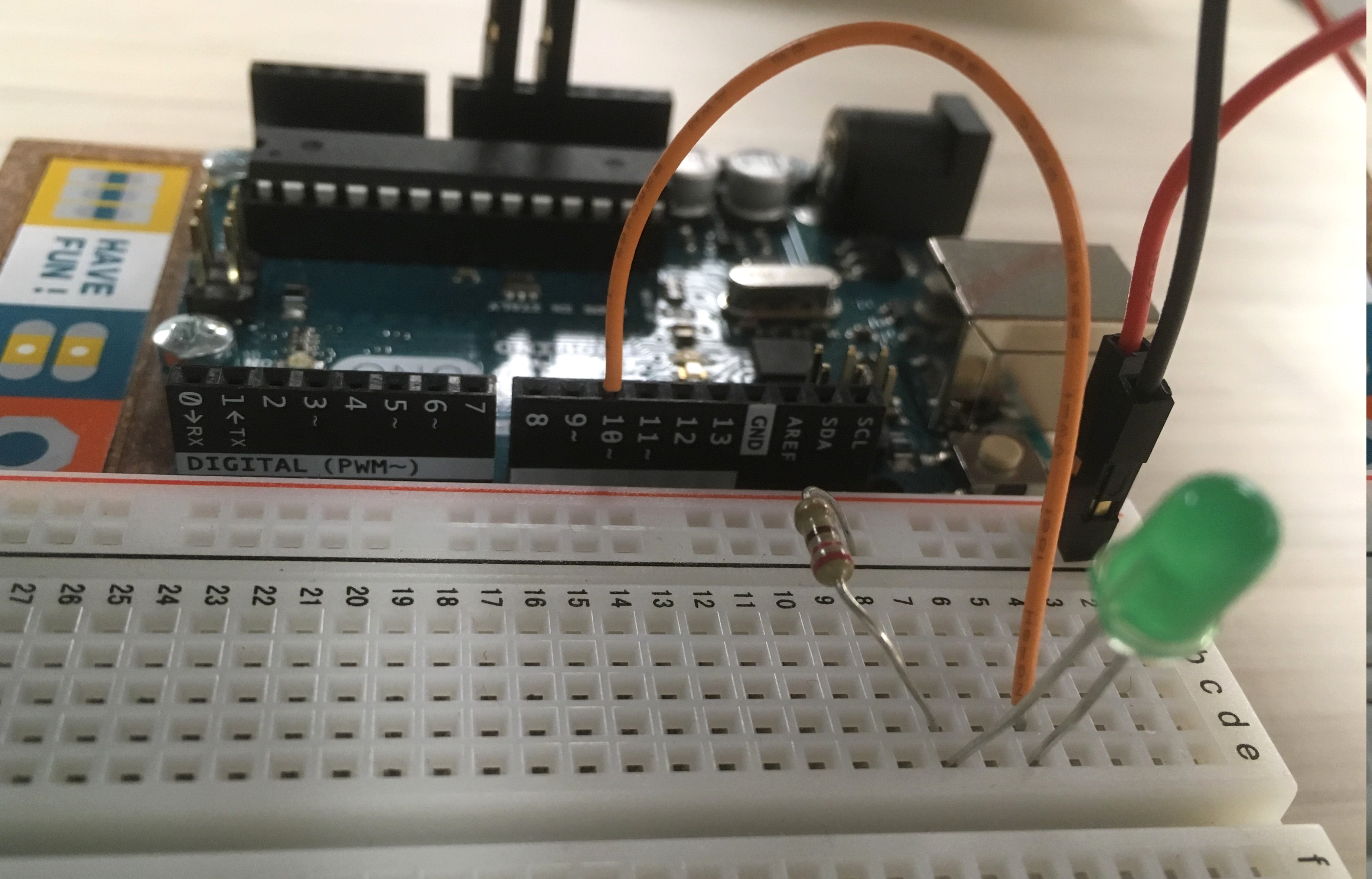
Connect the
anodewire to pin10on the UNO.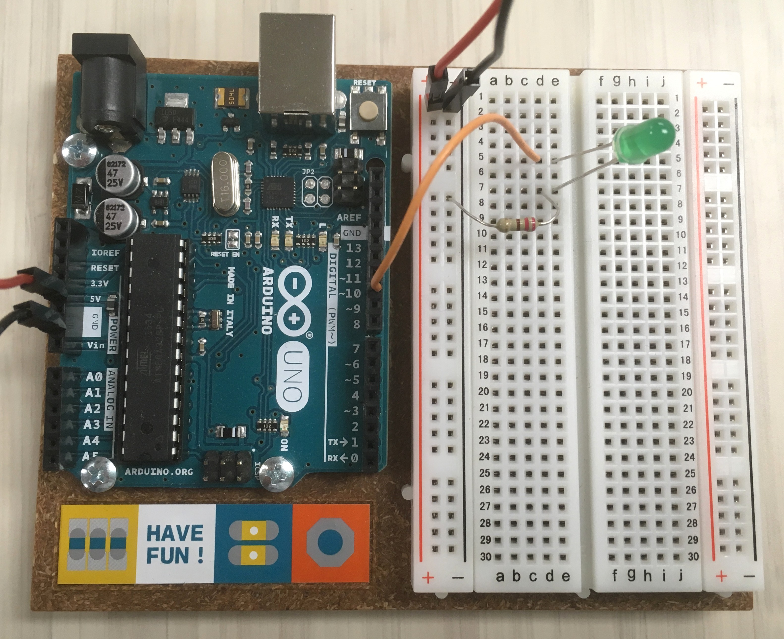
-
On the IDE
Blinksketch, replaceLED_BUILTINwith10. The basic code should look like:void setup() { pinMode(10, OUTPUT); } void loop() { digitalWrite(10, HIGH); delay(1000); digitalWrite(10, LOW); delay(1000); } -
Plug UNO into the usb, and click the upload arrow to load the sketch.
You should now have a beautiful Blinking LED!
3.3 - Extra credit
- make an interesting pattern blinking both the LED and LED_BUILTIN.
- add another LED and make them blink together.