Blink an LED
Building on our Blink skillz, lets build a LED circuit and control it with UNO!
Circuit; LED; Output Pins
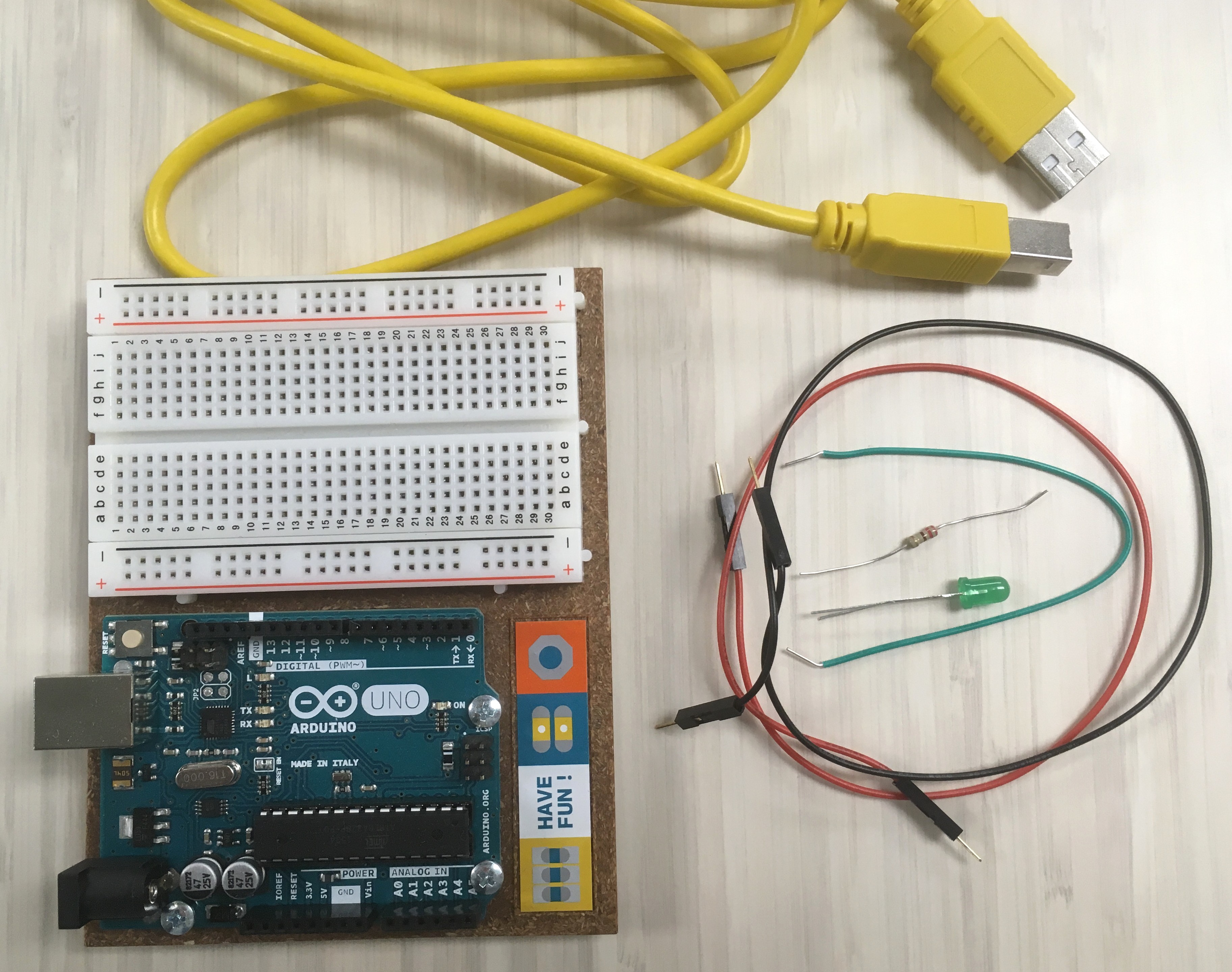
For this project you will need a breadboard, some jumper wires, a 220 or 330 ohm resistor, and an LED.
Know your LED: the longer leg is the anode and connects to positive voltage, i.e. + or 5V; the short leg is the cathode and connects to ground, i.e. - or GND.
Know your Resistor: resistors are marked by color bands, but they are often hard to read - you can check them with a multimeter.
First Circuit
With your board unplugged from your computer, start building a circuit on the breadboard:
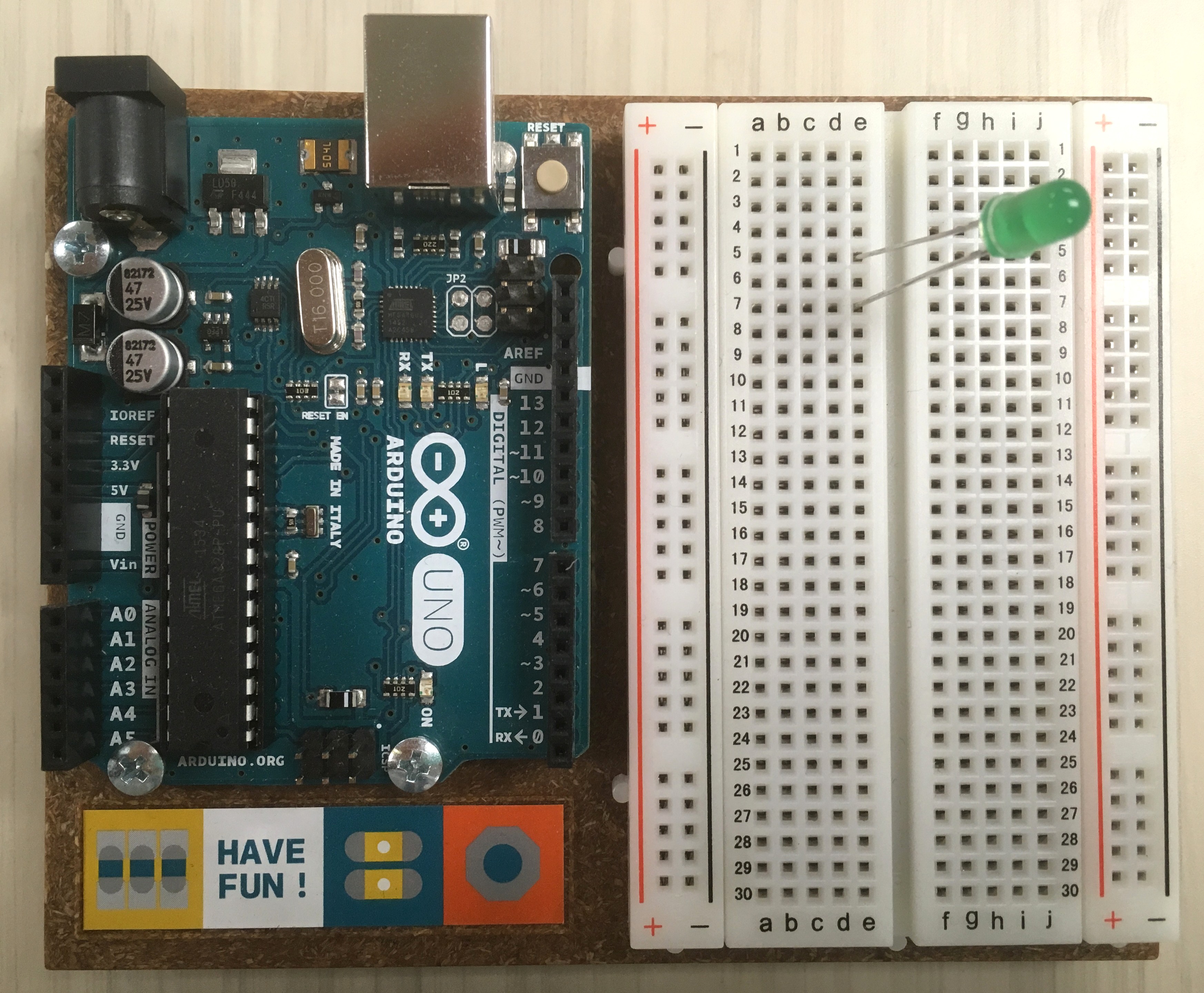
- Gently push the legs of your LED into two different rows on the breadboard. Remember which one is the long leg (anode)!
![LED legs added to breadboard rows 5 and 7]()
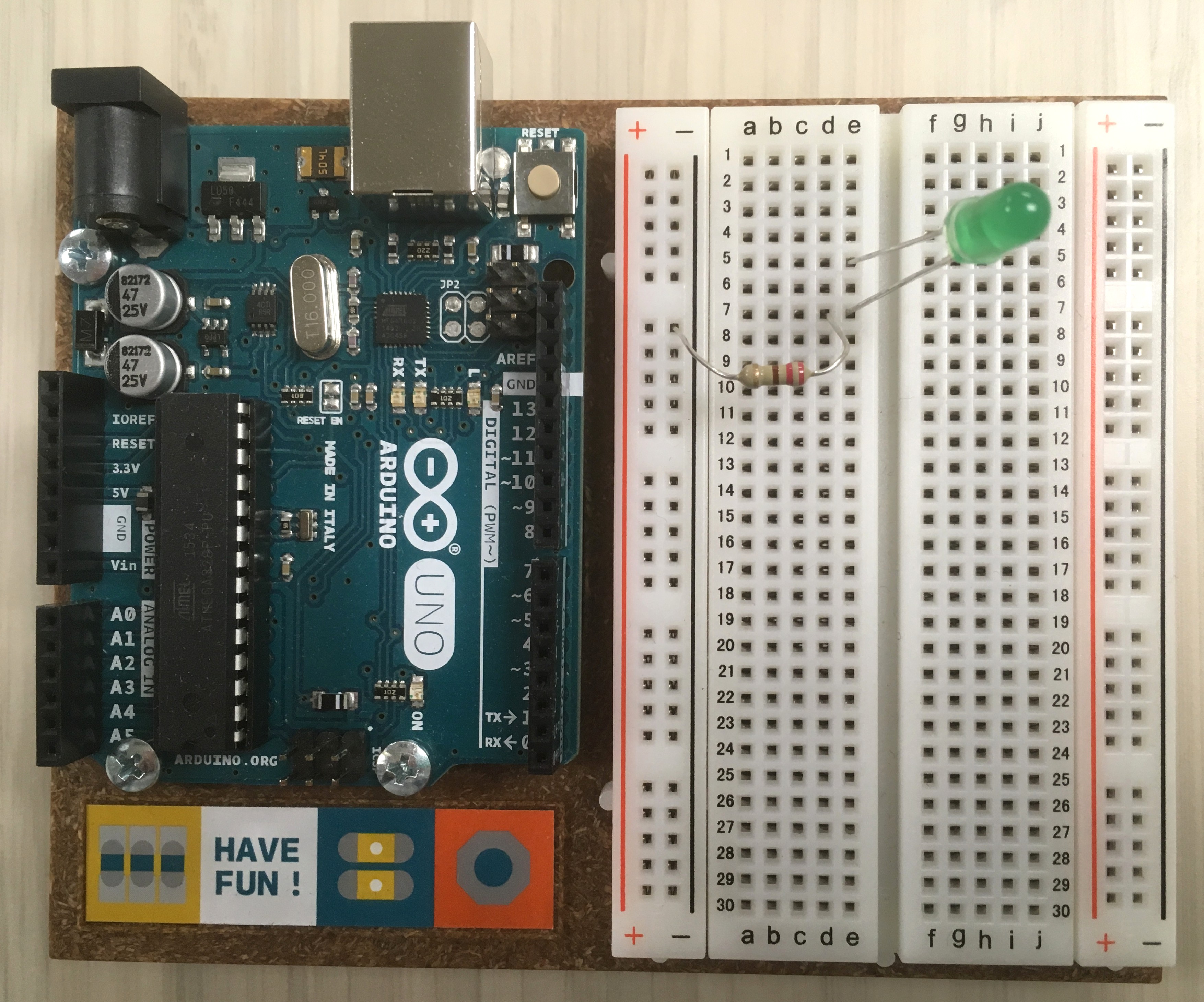
- Connect the LED
cathode(short leg) toGNDby inserting the legs of a 220 ohm resistor into the row and the-Rail.![220 ohm resistor added to breadboard connecting LED cathode to GND rail]()
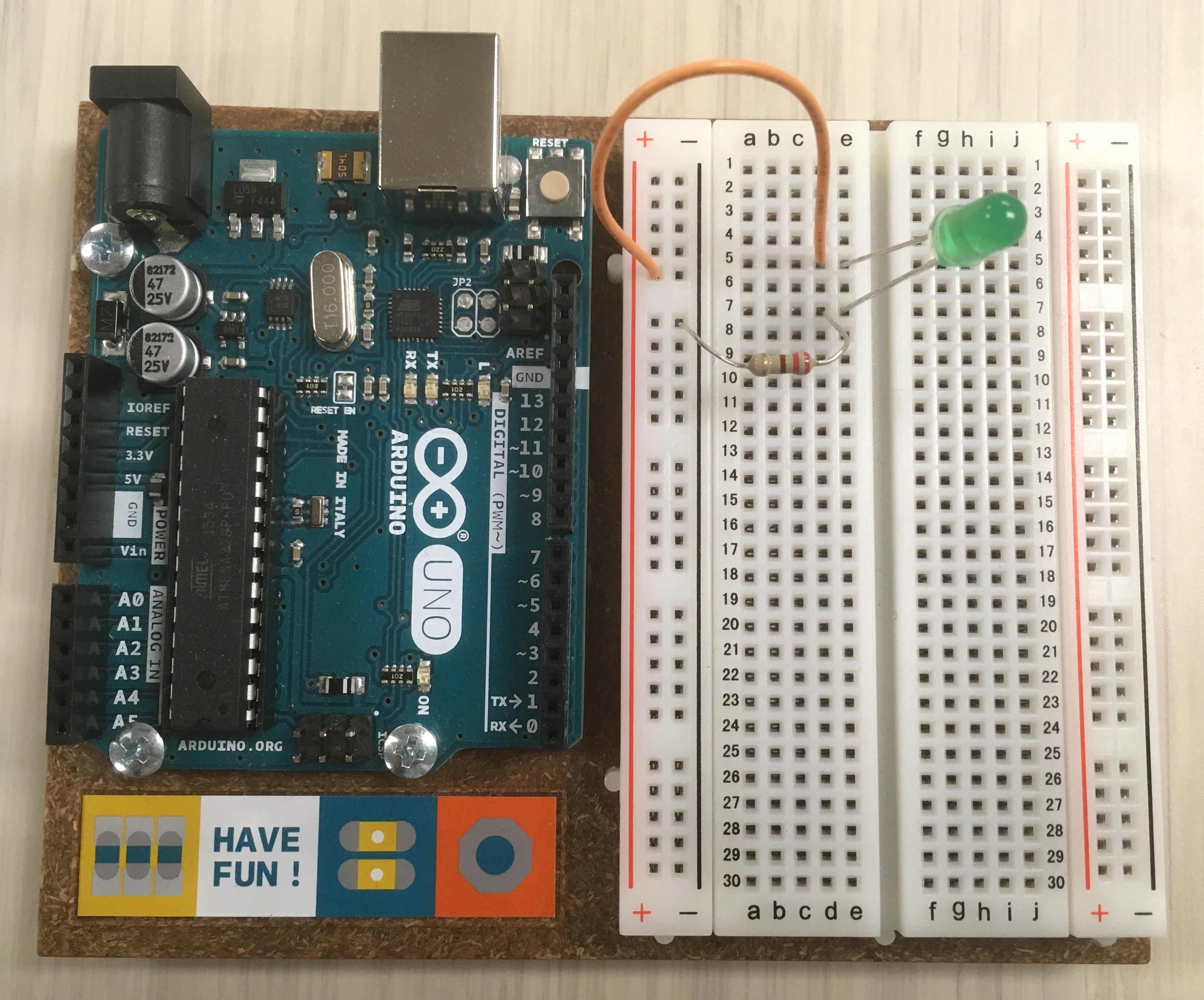
- Connect the LED
anode(long leg) to5Vby inserting a jumper wire into the row and the+Rail.![Jumper wire added to breadboard connecting LED anode to 5V rail]()
- Connect the breadboard to the UNO’s power supply:
- use a red jumper wire to connect the
+rail to the pin labeled5Von the UNO. - use a black jumper wire to connect the
-rail to any pin labeledGNDon the UNO (you have 3 choices).
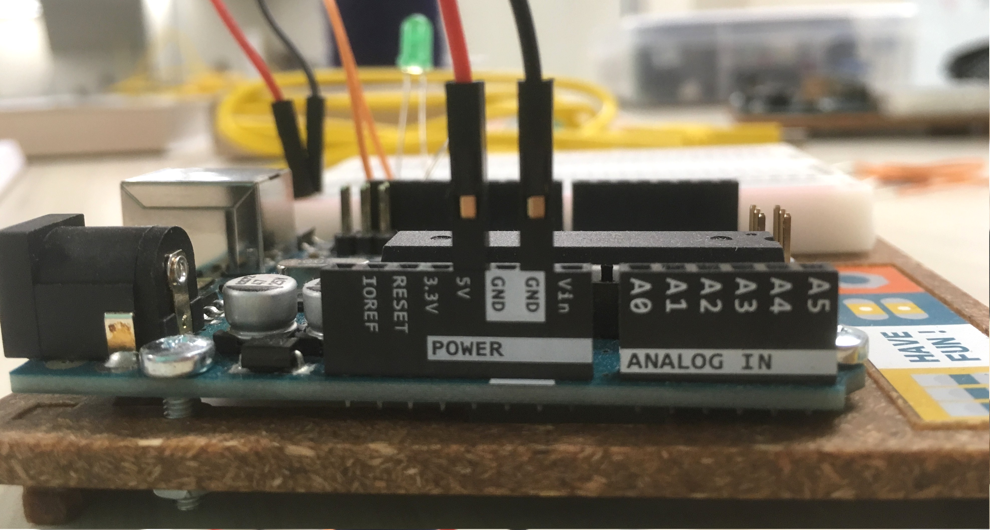
![jumper wires added to connect 5V and GND on the breadboard to UNO]()
![side view showing the GND and 5V pins on UNO]()
- use a red jumper wire to connect the
- Plug your UNO into your USB cable.
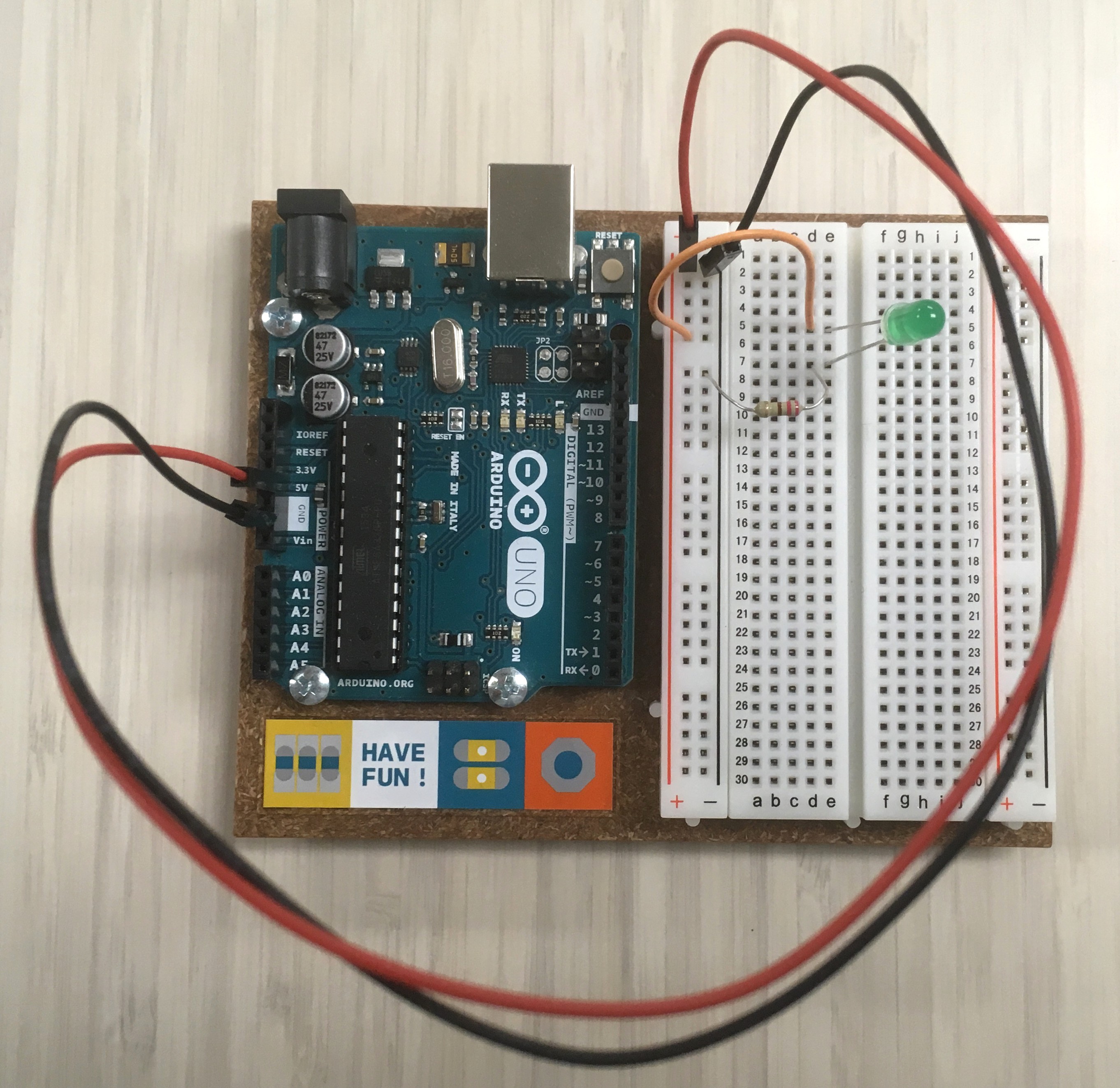
You should now have a beautiful glowing LED!
Blink it!
This circuit is drawing power from UNO, but it is not controlled by it. We need to connect the LED to a pin to make it an output–i.e. so we can start blinking! First, unplug the UNO from the USB–never modify your circuit while connected to power!
With your board unplugged from your computer:
-
Unplug the wire connecting the
anodefrom the+rail. -
Connect the
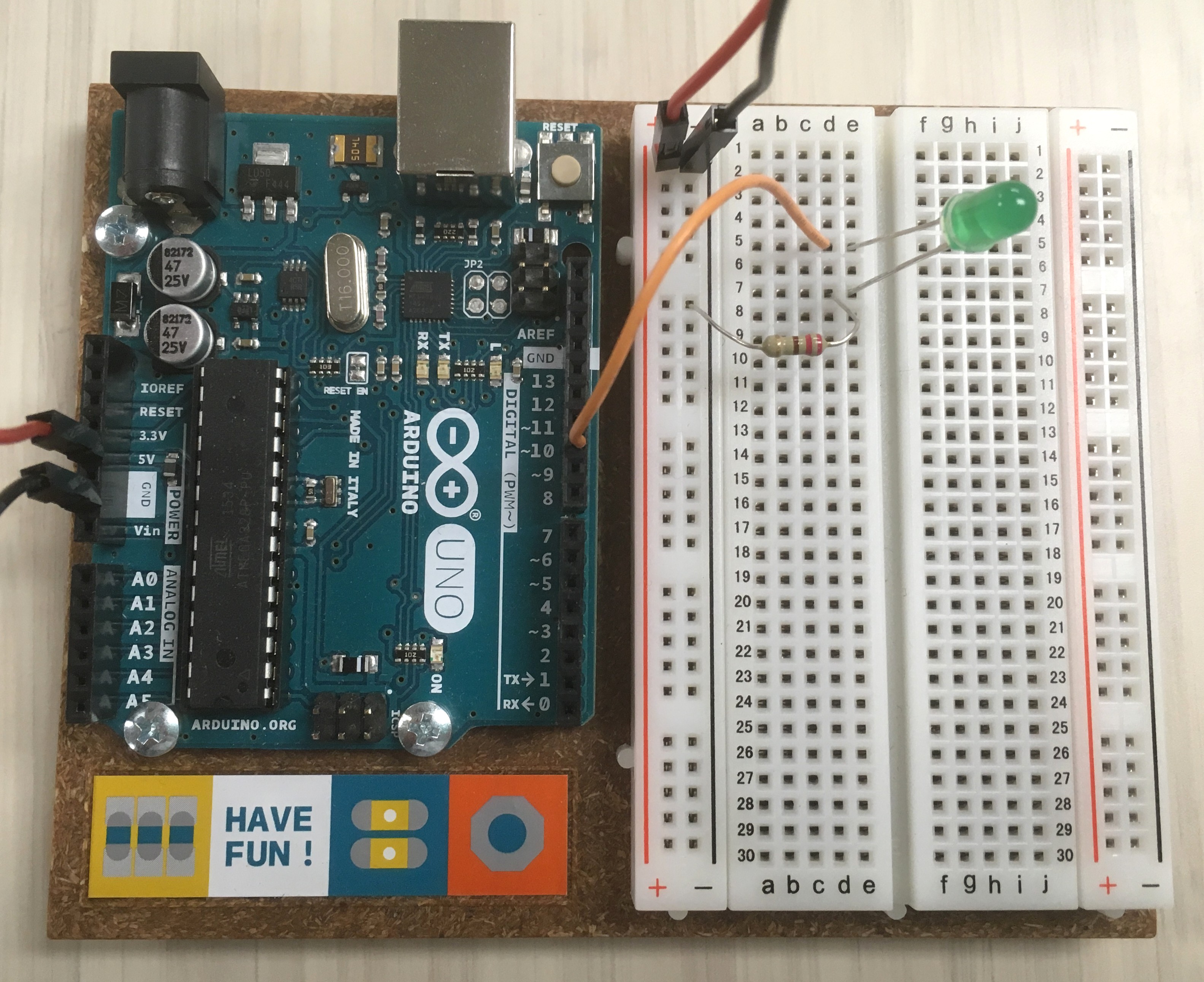
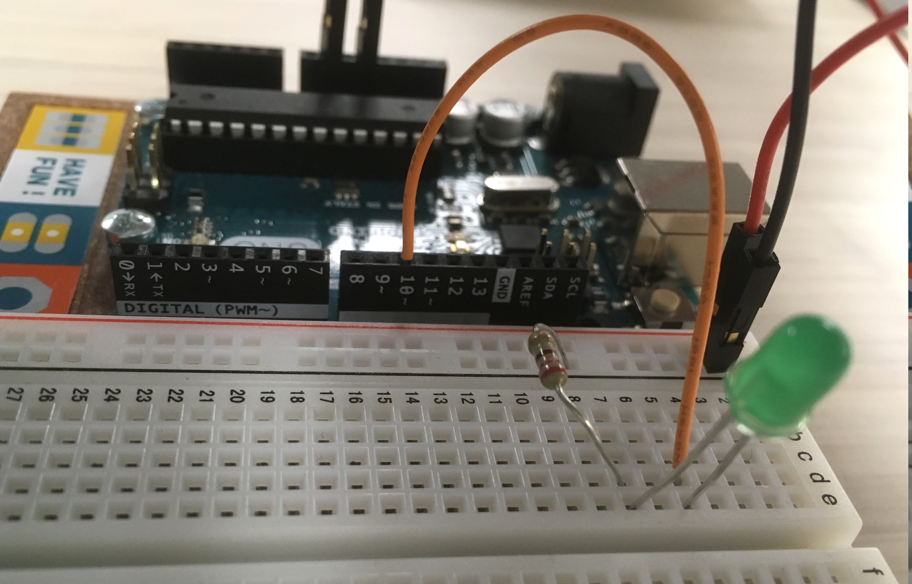
anodewire to pin10on the UNO.![jumper wire connecting LED anode to pin 10 on UNO]()
![side view showing pin 10 on UNO]()
-
On the IDE “Blink” sketch, replace
LED_BUILTINwith10. The basic code should look like:void setup() { pinMode(10, OUTPUT); } void loop() { digitalWrite(10, HIGH); delay(1000); digitalWrite(10, LOW); delay(1000); } -
Plug UNO into the USB, and click the upload arrow to load the sketch.
You should now have a beautiful blinking LED!
Extra Credit
The best way to learn is by messing around! Try altering your code and circuit. Remember: it is hard to break UNO!
- make an interesting pattern blinking both the LED and LED_BUILTIN.
- add another LED and make them blink together.