Light Theremin
Time to make some buzz! Let’s build a “light theremin” that changes pitch using a photoresistor.
Piezo; Photoresistor; Tone Function
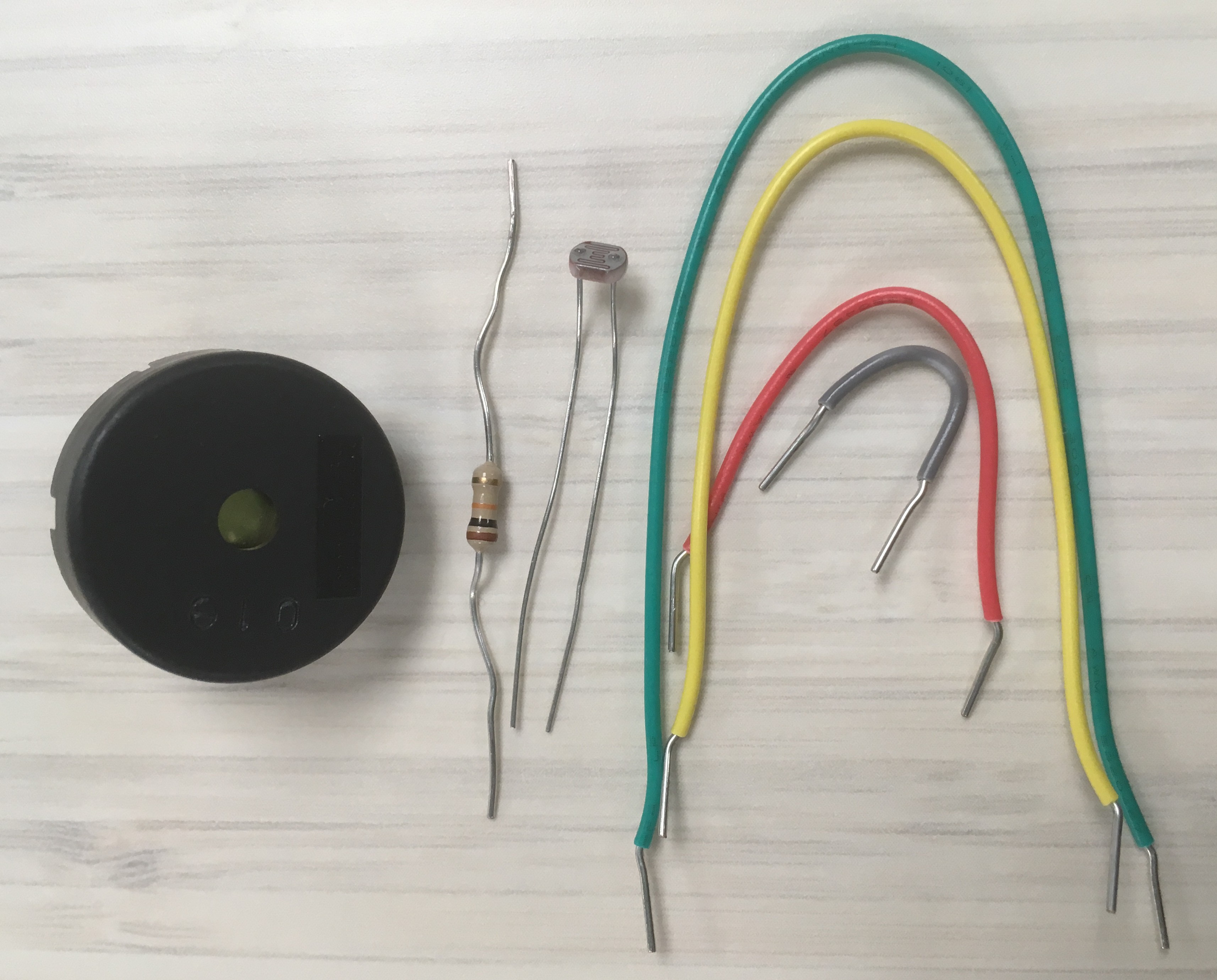
For this project you will need some jumper wires, a piezo, a 10k ohm resistor, and a photoresistor.
This time we are adding a sensor, the photoresistor, so that UNO can get input from the outside world, i.e. UNO can get interactive! The piezo provides the buzzing (output) and we control it by having UNO read the photoresistor.
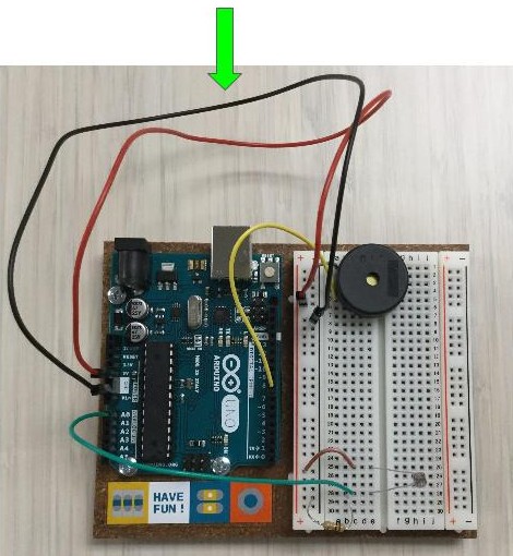
Light Theremin Circuit
Connect Piezo
-
Gently insert the pins of your Piezo into row one and five (or any two separate rows that they fit into, the key is to try to leave enough space to fit your jumper wires!).
![piezo being inserted into breadboard]()
-
Connect row one to the ground
-rail with a wire jumper (i.e. piezo to GND)![wire connecting breadboard GND to piezo]()
-
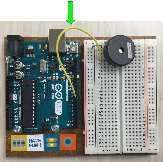
Connect row five to pin
8on the UNO using a wire jumper (i.e piezo to digital pin)![wire connects piezo to UNO pin]()

Connect Photoresistor
-
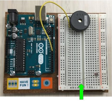
Insert the pins from the photoresistor in rows twenty-five and twenty-eight (or any two separate rows that will provide some space to work).
![photoresistor added to breadboard]()
-
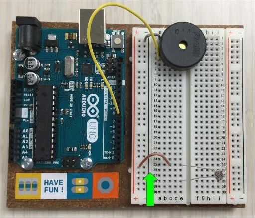
Connect one leg of the photoresistor (row twenty-five) to the power
+rail with a jumper wire. (i.e. photoresistor to 5V)![wire connecting photoresistor to breadboard power rail]()
-
Use 10k resistor to connect the other leg of the photoresistor (row twenty-eight) to ground
-rail (i.e. photoresistor to GND). This is called the pull down resistor, used to ensure we have a stead signal for the input.![resistor connects GND to photoresistor in breadboard]()
-
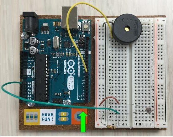
Connect the same leg (row twenty-eight) to Pin
A0on the UNO. (i.e. photoresistor to analog input)![wire connects photoresistor to UNO pin]()

Connect Power
-
Connect the ground
-rail to aGNDpin on the UNO with a power jumper wire. -
Connect the power
+rail to the5VPin on the UNO with a power jumper wire.![wires connect breadboard rails to UNO power pins]()
All ready to program…
Theremin Code
-
On the IDE, choose
File>Examples>StarterKit_BasicKit>p06_LightTheremin -
Plug UNO into the USB, and click the upload arrow to load the sketch.
-
The first few seconds the program calibrates the photoresistor, so move your finger over and back to change the amount of light falling on the sensor.
The buzzing will start soon - Enjoy!
Make the Buzz Less Annoying!
Find at the line that says int pitch = map(sensorValue, sensorLow, sensorHigh, 50, 4000);
This function maps our photoresistor readings (sensorValue) to a number between 50 and 4000, which will be output as a tone in the piezo.
The lowest possible sensor reading will translate to a tone of 50, the highest to 4000.
Swap the range so that it says 4000, 0.
What does this do?
Experiment
Keep editing and experiment!
Try changing a few values in the loop(), such as:
- range of pitch: change
4000, 0to something else - tone length: change the third number in the
tone()function - loop delay: change the final
delay()time
Try loading other sketch examples that work with this circuit:
File>Examples>Digital>toneMelody- Download arduinoTeaching examples. Look for
lightThereminBasic.ino, a heavily annotated version ofp06_LightTheremin.
Extra Credit!
Put your vast knowledge of Arduino to use and build a new project based on what we did so far. Suggestions:
- Build a blinking lights display with multiple LEDs.
-
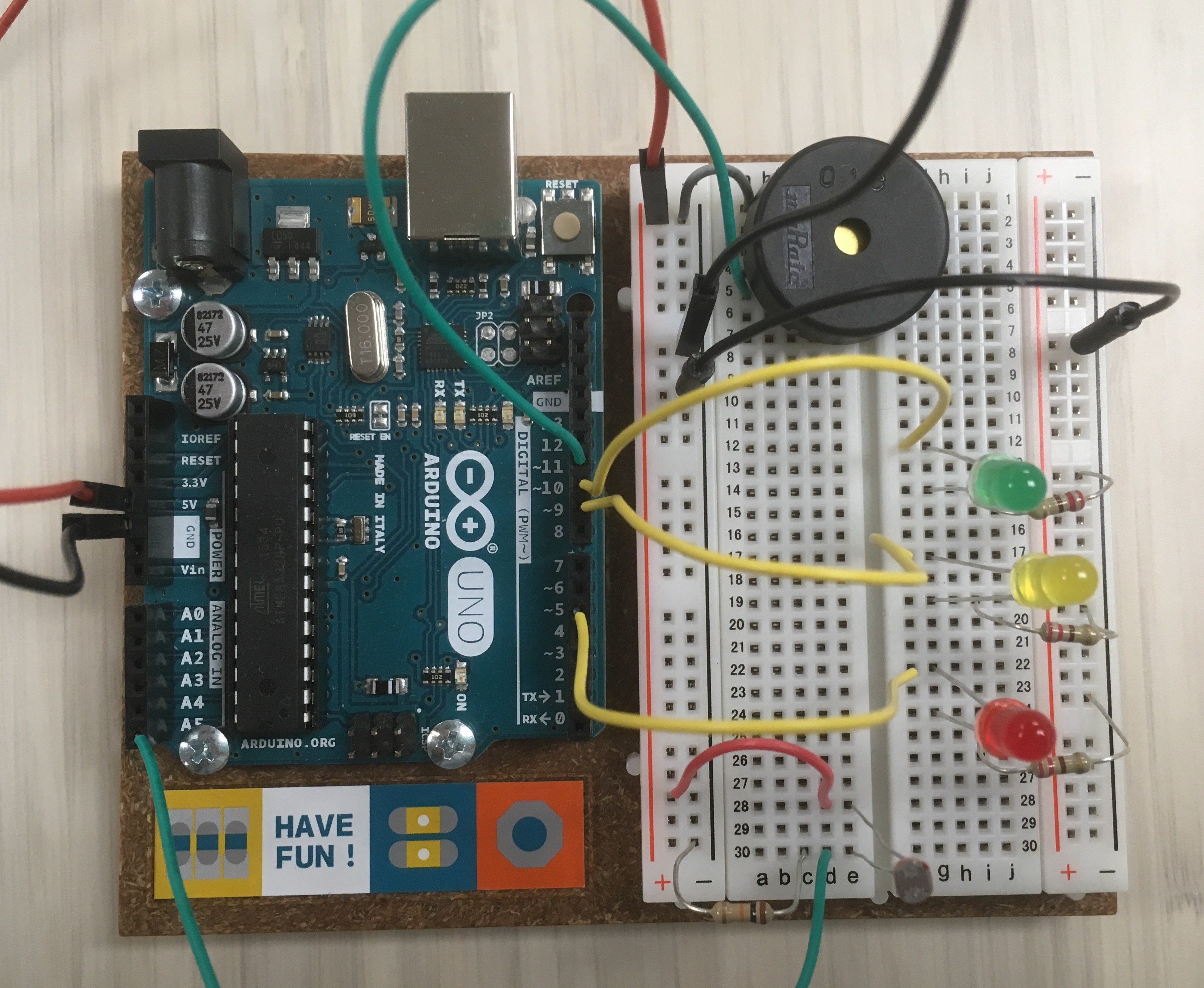
Combine blinking LEDs and the light theremin (note: tone() interferes with pin 11 and 3, delay() interferes with pin 5 and 6, so you can end up with odd results).
![UNO with light theremin circuit with LEDs added]()
-
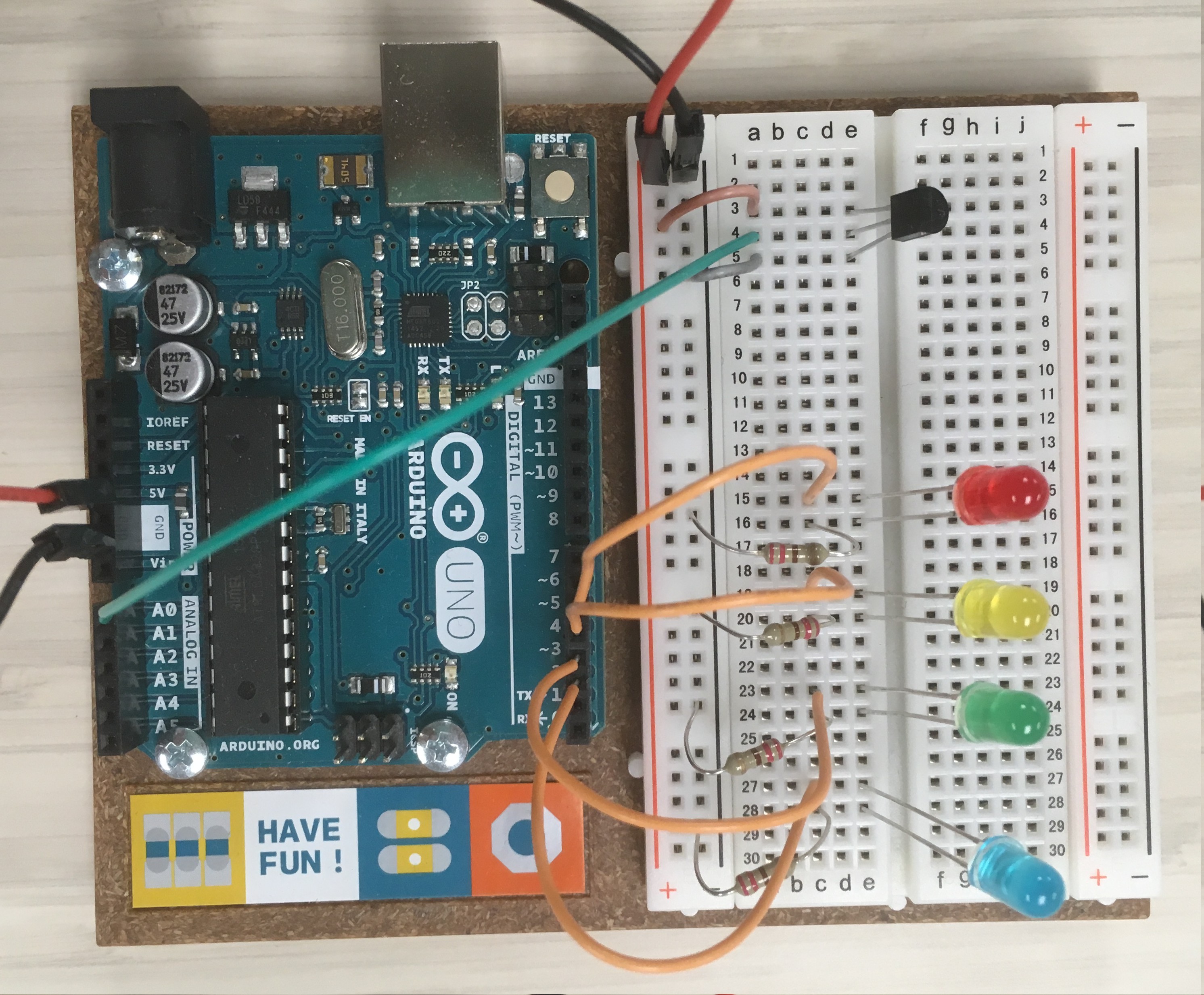
Use another sensor to set variables for blink or theremin, for example a potentiometer or temperature sensor.
![temp sensor and LEDs added to light theremin circuit]()